Live Load Distribution and Stability of Spliced Bridges
September 2024 – June 2025
Advisors
Dr. Todd Helwig
Dr. Matthew Hebdon
Collaborators
Paul Tackett
Tanakorn Ngamjarungjit
Dr. Aidan Bjelland
Dr. Mojtaba Aliasghar
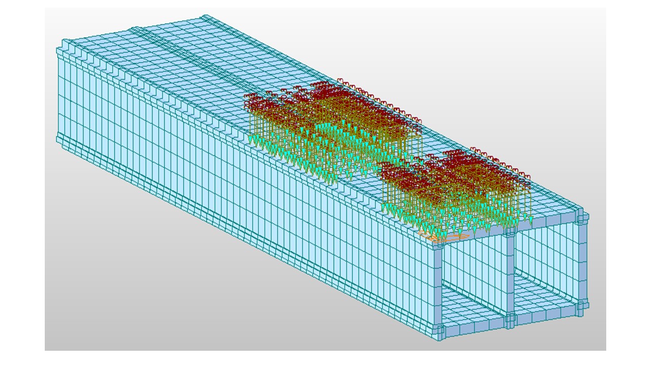
Recent advances in Texas design and construction procedures have led to spliced concrete girder sections that result in significant increases in the bridge lengths that are viable for concrete bridge systems. These trends towards longer bridge spans lead to significant increases in the girder slenderness, thereby introducing concerns about the stability of these spliced concrete bridge systems. The requirements for bracing in these girders to ensure stability and predictable response during construction have not been established. While the current practice employs diaphragms at the locations of splices and supports, the requirements and even the need for some of these braces will likely be questioned in the future based upon the transitions in construction practices that removed diaphragms in the 1980s. The applicability of AASHTO live-load distribution factors on these girders is also highly questionable. This project focuses on the stability of long-span prestressed concrete I- and U-girders during erection and construction. The research considers the distribution of live load in the completed bridge as well the role of diaphragms in stability and live load distribution, and develops methods of analysis of the girder behavior.
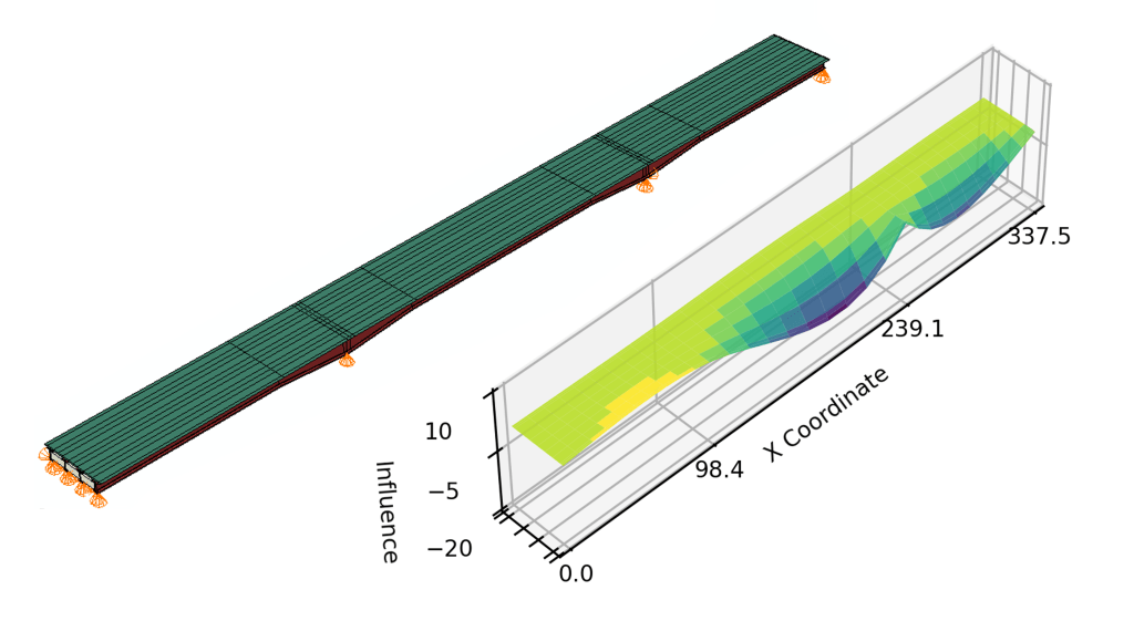
In this project, my focus is on the live load distribution in spliced I-girder bridges. I am currently developing Python scripts to develop a refined finite element model of the representative spliced bridges of Texas. I am using an influence surface based analysis procedure for AASHTO live loads for computational ease. The study will involve parametric analyses to understand the live load distribution in these bridges and identify the role of diaphragms in the distribution.
Develop Deck and Overhang Design Guidelines for Sound Walls and Other Heavy Loads
September 2021 – August 2024

Advisors
Dr. Eric Williamson
Dr. Todd Helwig
Dr. Michael Engelhardt
Collaborators
Tanakorn Ngamjarungjit
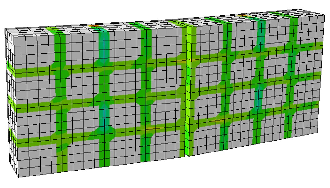
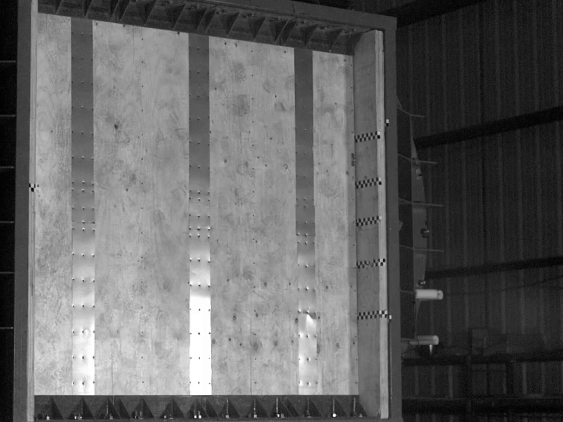
The behavior of bridge overhangs with sound walls and other heavy loads are not well understood. Many bridge owners have guidelines on sizing and detailing deck overhangs, and simple methods of distributing railing load to girders, generally based on rules-of-thumb that have been developed based upon experience. In this project, we investigated the behavior of a wide range of slab-girder bridges with heavy overhang loads. The study included I-shaped and U-shaped prestressed concrete girders, as well as steel I-shaped and tub girders. Detailed three-dimensional Finite Element (FE) models were developed considering a wide range of geometries and details. Detailed parametric studies were conducted on a wide range of bridges reflecting each girder type. Based upon the data gained on the parametric studies, Railing Load Distribution Factors (RLDF) were developed using a symbolic regression algorithm for the design of girder-slab bridges. These factors represent the proportion of railing load to be applied to a girder when performing a line girder analysis. The proposed equations predict the effects of railing dead load on girders and result in safe and economical designs when compared to current practices. In addition to evaluating the moments and shears induced in the girders by the overhang loads, an evaluation of the deck design considering vehicular impact on the wide range of bridge rails was conducted. Standard deck overhang details currently used by TxDOT were evaluated for the 6 different rail systems used in Texas. In addition to the 8.5 in. deck commonly used in Texas, 10 and 12 in. decks were also considered. The decks were evaluated for Serviceability considering deck cracking and deflection; however, vehicular impact (strength) controlled the design of the overhangs.
Response of Steel Stud Walls to Blast Load
August 2022 – December 2022
Advisor
Dr. Eric Williamson
Collaborators
Beverly McCarthy
Danielle Krug
Loveleen
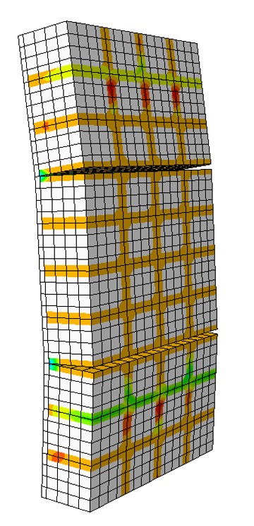
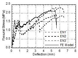
This research project was carried out as part of the course CE 384T – Blast-Resistant Structural Design. Our team tested a steel stud wall with gypsum sheathing facing the blast wave and a composite steel-plywood sheathing on the other side. The wall resisted a peak pressure of 5.83 psi (40.2 kPa) with impulse of 41.8 psi-ms (288.2 kPa-ms). The specimen was designed to resist flexure during the positive impulse of blast load. The specimen was cast in the Ferguson Structural Engineering Laboratory (FSEL) in UT Austin.
The specimen was tested in the shock tube testing facility of ABS Consulting at San Antonio, TX. The wall performed very well in terms of containing the flying debris which is more critical in blast events. The utility holes in the cold-formed steel studs were ultimately responsible for the failure eventually leading to the pull-out of sheathing. Simple single-degree of freedom (SDOF) models representing the one-way flexural behavior predicted the peak displacement at the center of the wall.
Structural Behavior of Tall Haunches in TxDOT Beam and Girder Bridges
January 2021 – August 2021


Advisors
Dr. Eric Williamson
Dr. Todd Helwig
Dr. Michael Engelhardt
Collaborators
Nidhi Khare
Zhenghao Zhang
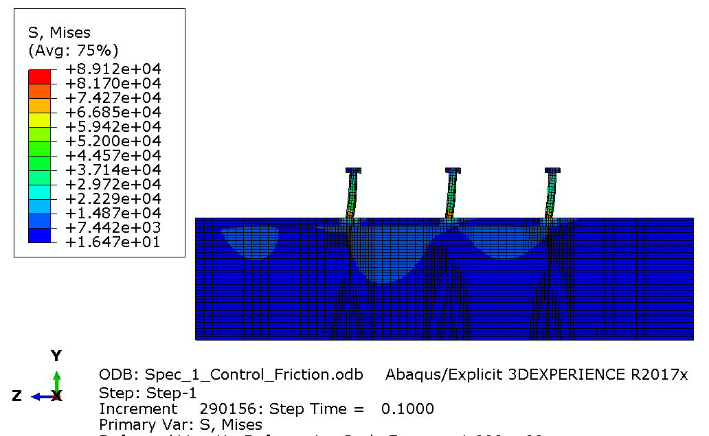
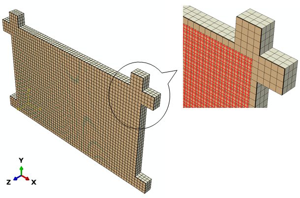
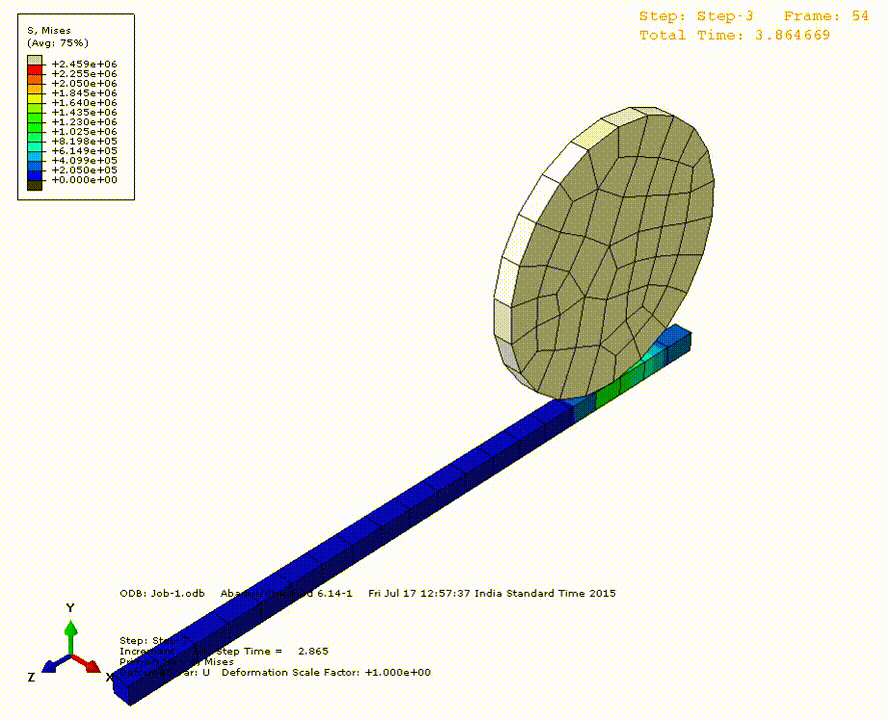
Deck haunches are commonly used on both prestressed concrete and structural steel girder bridges. The haunch is the area between the top of a bridge girder and the bottom of the concrete deck. A primary function of the haunch is to maintain a uniform deck thickness. Haunches are often needed to account for camber and cross-slope. Due to unusual geometric situations or design errors, beam and girder bridges sometimes require tall haunches, which calls into question the overall constructability and horizontal shear transfer between the girders and the deck.
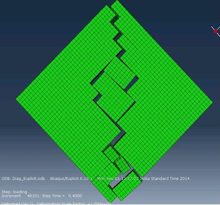
In this study, we studied the haunches with various details using push-out tests. We also developed finite element models of the tests to validate and perform parametric analyses. My major contribution in this project was in the development of initial finite element models and testing two specimens at the Ferguson Structural Engineering Laboratory.
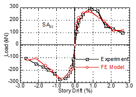
Effect of In-Plane Damage on Out-of-Plane Response of FRCM Strengthened Masonry Infilled RC Frames
May 2014 – October 2015
Advisor
Dr. Durgesh C.Rai
The out-of-plane (OP) strength of masonry infills is reduced when damaged under the action of the in-plane (IP) forces. A strengthening approach using a fabric-reinforced cementitious matrix (FRCM) was proposed for improving the OP strength of damaged infill walls. A finite-element (FE) model of a reinforced concrete (RC) frame, infilled with FRCM-strengthened masonry, was developed and validated using experimental results and analytical predictions. Interaction curves representing the interplay between in-plane damage and out-of-plane response were generated for unstrengthened (ordinary) and FRCM-strengthened infill walls using FE analysis.
We introduced a novel definition of damage state for fragility analysis that can consider the effect of in-plane damage and out-of-plane strength for masonry infills. The proposed methodology helped identify critical infills that require strengthening.
Reconnaissance Survey of 2015 Nepal Earthquake
May 2015 – July 2015
Advisor
Dr. Durgesh C.Rai
Collaborators
Dr. Vaibhav Singhal
Lalit Sagar
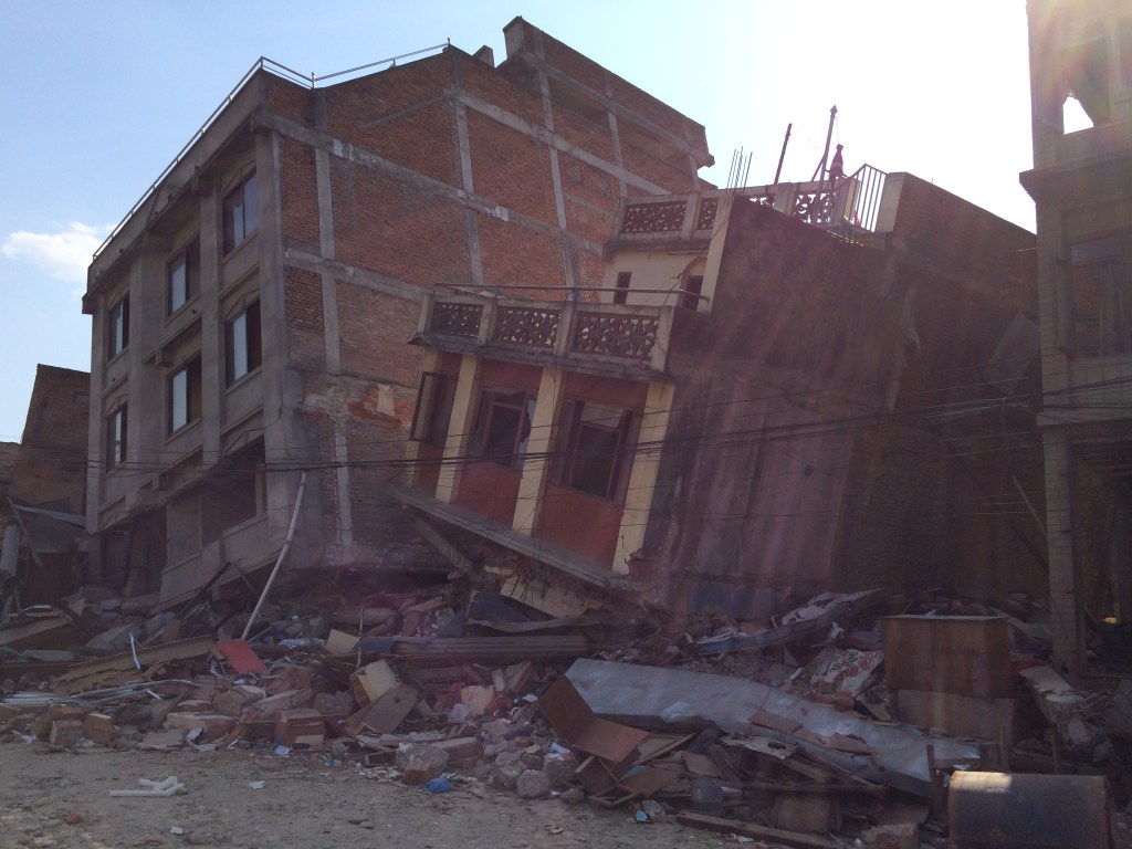
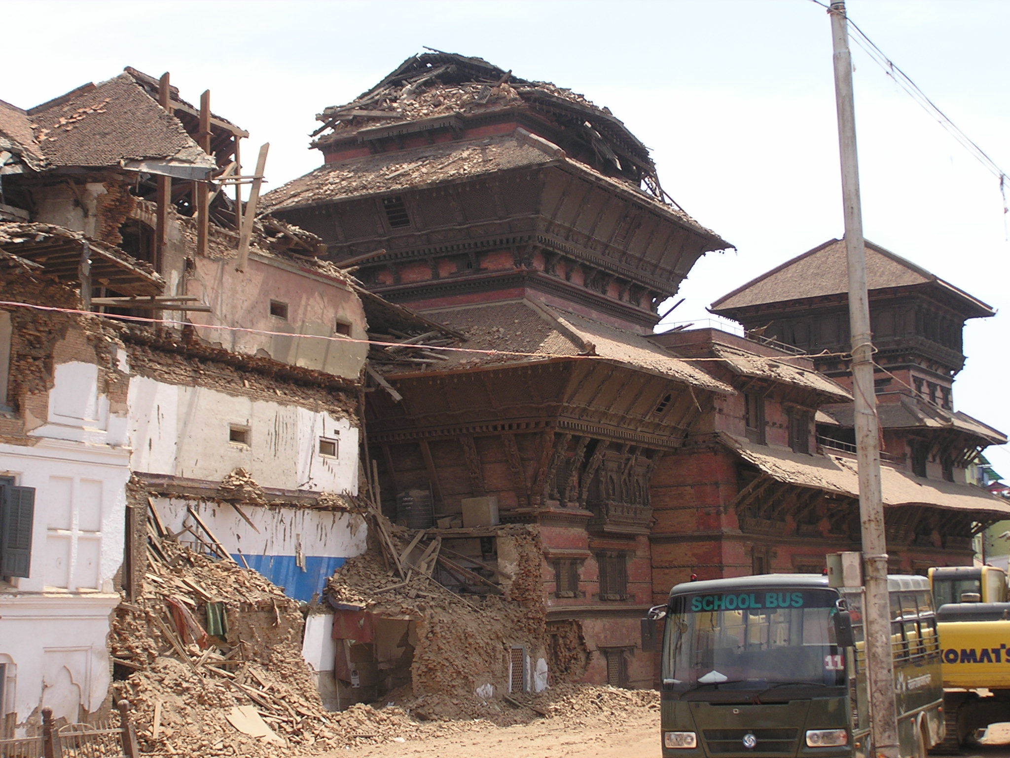
The M7.8 earthquake of April 25, 2015 struck at 11:41 am IST with its epicenter located in Gorkha district (28.15°N 84.7°E) in the central Nepal, about 80 km NW of the capital Kathmandu. It was a shallow focus event (depth 15 km), which was felt in India, Nepal, Bhutan, Bangladesh and China. In Nepal, this earthquake caused unprecedented loss of life and devastation. The worst effected regions are Kathmandu, Bhaktapur, Nuwakot, Sindhupalchok, Dhading and Gorkha. Strong aftershocks of magnitude 6.6 and 6.7 were also felt within a day of the main shock. A large part of the northern India, especially eastern UP, Bihar and north Bengal, also experienced intense shaking during this earthquake. Total deaths were reported as 7,913 in Nepal, 80 in India, 25 in China and 4 in Bangladesh.
As part of the reconnaissance team from the Indian Institute of Technology Kanpur, we undertook a survey of the earthquake affected regions during May 3 to May 8, 2015 and visited major towns in Bihar (India) and Nepal. We discovered a great majority of buildings seriously lacked earthquake-resistant features which are so essential for a satisfactory seismic performance in the design level shaking. We observed various failure patterns of modern reinforced concrete buildings, unreinforced masonry buildings and iconic heritage structures in Nepal. These observations were correlated with the ground motion characteristics, geology of the region and building code compliance.
Some short-term projects
Automation of Live Load Application on Slabs
2018
A program was developed in VB environment for applying pressure loads due to wheel loads dispersed through earth fill and pavement layers on slabs in MIDAS Civil software
Simulation of Wheel Motion on Rail
July 2015
A finite element simulation of wheel movement on a rail was developed for a researcher working on ballast-less tracks.
Micro-modeling of Masonry
2014
Masonry was modeled as discrete blocks with cohesion and friction interfaces in horizontal and vertical bed joints. A MATLAB program was developed to generate the input file for the model in ABAQUS.